A hillside, three ways
The vertical on a slope page solves a mast on an infinite tilted plane. The levee page reflects each far-field ray off a faceted profile. Between the two releases that carried them, the faceted model grew a second composer that shadows, reflects off tilted mirrors and diffracts. This page puts all three on one hill so the progression can be seen rather than described: what each generation adds, what it got wrong, and what stayed fixed throughout.
The site is a reader’s: a plumb quarter-wave with four radials an inch above
the ground, mid-slope on a 45° hill between a plain below and a plateau above,
7.1 MHz, soil εr 13 / σ 0.005 S/m. The hill on this page is 400 m of relief,
9.5 wavelengths, so the mast stands 200 m above the plain. Elevation is
measured from the true horizontal; downhill looks out over the plain and
uphill looks into the slope toward the crest. The scripts that made every
figure and number are in the repository under scratch/slope-study/
(probes 12, 16, 17 and 18), and all four far fields come from one cache.
Three generations on one hill
Section titled “Three generations on one hill”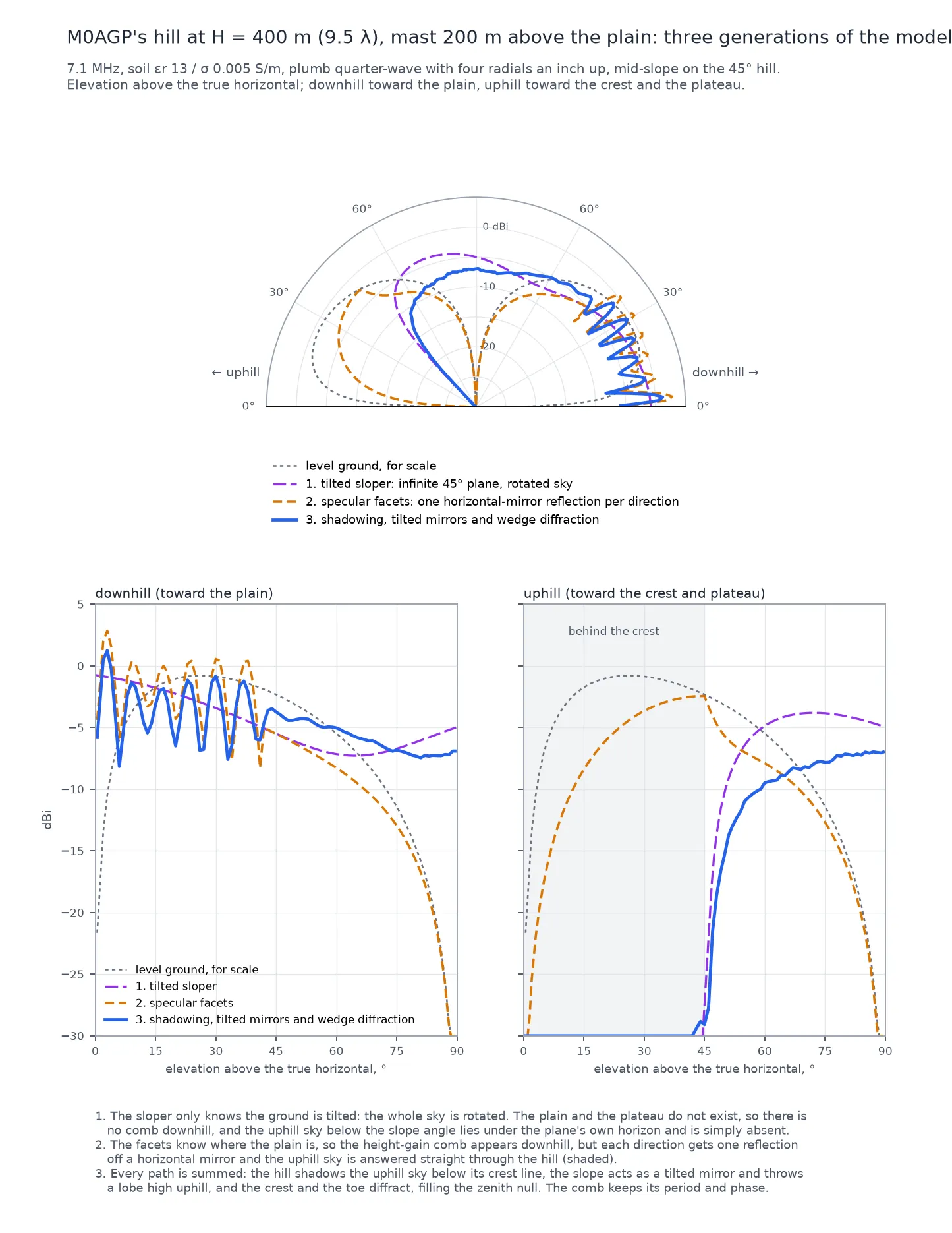
1. The tilted sloper. The antenna is solved on level ground and read out through a sky rotated by 45°. It knows one thing about the site, that the ground is tilted, and it gets the consequences of that one thing right: the downhill lobe leans out over the plain, and the uphill sky below the slope angle lies under the plane’s own horizon and is simply absent. But there is no plain in this model, so there is no reflection from the plain and no comb. And there is no crest either, so the absence of the uphill sky is right for the wrong reason: the plane goes on rising forever.
2. The specular facets. The profile is now a plateau, a 45° slope and a plain, and each far-field direction reflects once off the facet its specular point lands on. The plain exists, so the plain’s reflection exists, and the downhill cut acquires the height-gain comb of an antenna 200 m up: a peak every few degrees, each one the plain’s image adding to the direct ray. That comb is real, and the diffracted model keeps its period and phase exactly. But every reflection is off a horizontal mirror lifted to the facet’s height, and nothing is ever in the way. Uphill, below the crest line, the model reports −22 to −4 dBi through 45 degrees of hillside.
3. The diffracted composer. Every path is summed rather than one per direction: direct radiation, shadowed by the profile; every valid reflection, single and double, with the source imaged across each facet’s own tilted plane; and UTD wedge diffraction at the crest and the toe. Three things change on the page, and each is a different piece of physics:
- The shadow. Below 45° uphill the field collapses by 22 to 35 dB and falls off the chart within 15° of the horizon. The edge is a wall at the crest line. This is the correction the composer was built for.
- The tilted-mirror lobe. From 60° to 85° uphill the diffracted model is brighter by 5 dB at 75° and 14 dB at 85°. A ray that strikes the 45° slope leaves at the angle a tilted mirror gives it, which throws radiation into the high uphill sky where a flat mirror at the same height put none.
- The zenith. A plumb vertical radiates nothing straight up, so the null at 90° in the first two models is the antenna’s own. The diffracted field from the crest and the toe fills it, to about −7 dBi here. Read that it fills, not how far: a filled null is the least certain number on the page.
What stayed fixed. The feed impedance is identical in all three, 39.60 + 16.68j Ω. The current solve is the flat Sommerfeld one at the antenna’s own soil in every generation; only the far-field composition changed. The comb’s period and phase did not move either, which is the plain’s reflection being the same reflection in generations two and three.
The 2 dB the comb lost
Section titled “The 2 dB the comb lost”The downhill comb sits 1.4 to 2.2 dB lower in the diffracted model than in the specular one, across the whole band from 3° to 30°. That is not diffraction and it is not the toe’s double bounce: switching the composer’s wedge terms off leaves the comb where it is (−1.67 dB mean against the specular page, versus −1.66 with them on), and keeping only single reflections leaves it there too (−1.63 dB). Shadowed direct radiation alone matches the specular page’s comb to 0.1 dB on average. The shift lives in the single reflections.
The plain’s facets are horizontal, so tilting the mirrors cannot change the plain’s reflection. What changed is the count: the specular composer allowed one reflection per direction, off the facet its specular point landed on, and the diffracted one sums every valid path. The slope facets under the mast now also reflect into the downhill sky, and their contribution interferes with the plain’s. That is the model becoming more complete rather than less accurate, and the unmoved null positions are consistent with it. The same term also images each segment of the antenna separately instead of using one reference height, and the two effects have not been separated; doing so would need a hook the composer does not have.
The same hill at five heights
Section titled “The same hill at five heights”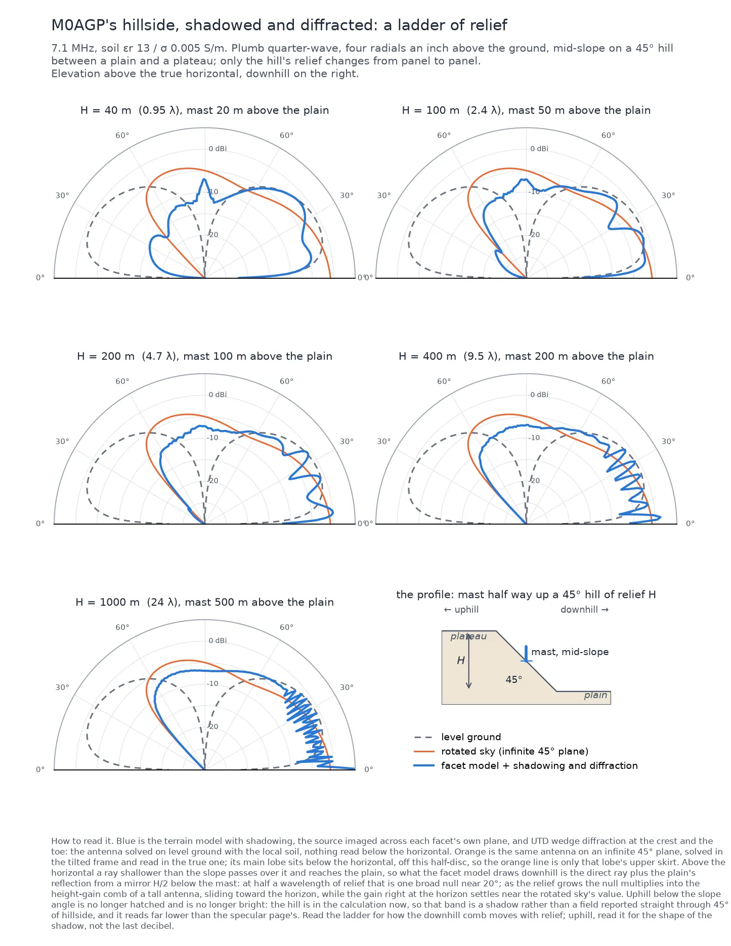
The 400 m hill is one rung of a ladder. At 40 m, just under a wavelength, the plain’s reflection makes one broad null near 20° downhill; at 1000 m it is a fine comb sliding toward the horizon, and the gain right at the horizon settles near the tilted sloper’s value. That is the height-gain of a tall antenna and diffraction does not soften it. Uphill, the band below the slope angle is a shadow on every rung, and the crest’s lobe above it grows with the relief. Read the ladder for how the comb moves; read the uphill side for the shape of the shadow, not its last decibel.
Which model for which site
Section titled “Which model for which site”- A mast on a long uniform slope, far from any crest or valley: the tilted sloper on the slope page. Its answer is exact for the site it describes, and the comb and the shadow are not things that site has.
- A mast at a crest, on a bench, or anywhere the ground changes slope within a few wavelengths: the faceted terrain, and the diffracted composer is its default. The specular composer survives as the drag-time field on the workbench because it costs 17 ms where the diffracted one costs about a second; the corner of each polar chart says which one is on screen.
- A mast right on a crest edge is inside that edge’s near zone, where the wedge is the weakest assumption in the calculation. A metre or two back from the break is both the better model and, probably, the better antenna.