A vertical on a slope
A question that comes up on the forums every season: my vertical is on a hillside — the radials follow the slope, none of it is level. What does that do? The instinct is that the radials being “not flat” must matter. For a mast standing normal to the slope it does not, and seeing why turns the whole problem into one ordinary solve plus a change of viewpoint. That case is worked first. A mast that is plumb, with its radials still following the slope — the more common build, and usually what the question means — is a different antenna, and it gets its own section below.
Everything below is momwire on the workbench’s catalog buried-radial
vertical — a quarter-wave over four radials buried 15 cm, soil εr 13 /
σ 0.005 S/m, 7.1 MHz — cut to resonance (0.953 of the nominal quarter-wave,
68 Ω resistive; the nominal cut reads 76+40j over this soil, electrically
long, which is what anyone trimming the antenna would remove). The scripts
that produced every number and both figures are in the repository under
scratch/slope-study/; each regenerates its table in about ten seconds.
The frame is the ground’s, not gravity’s
Section titled “The frame is the ground’s, not gravity’s”Put the observer on the slope. In the ground’s own frame the interface is a flat plane, the mast stands normal to it, and the radials lie at constant depth below it. That is exactly the level-ground antenna. The soil the radials couple to is the soil under them, and relative to that soil they are as flat as they ever were. The feed impedance is the level-ground value to the digit, and so is the current distribution.
What changes is where the sky is. A slope of angle s tilts the ground plane, so a direction at elevation ψ above the ground in the downhill azimuth is at true elevation ψ − s above the horizon, and in the uphill azimuth at ψ + s. Any direction that falls below the tilted plane is inside the hill. One solve, then a rotation of the read-out.
The elevation cut
Section titled “The elevation cut”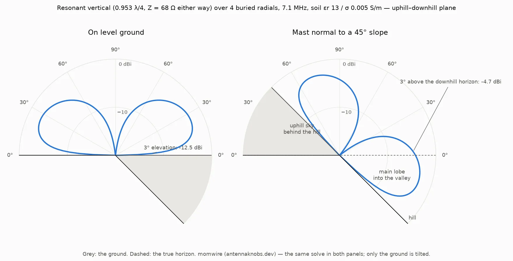
The left panel is the familiar picture: a ground-mounted quarter-wave over lossy soil, main lobe 27° up, −12.5 dBi at 3°. The right panel is the same solve with a 45° ground line drawn through it. Three things happen at once:
- The main lobe points into the valley. Its 27° takeoff above the ground is 18° below the true horizon on the downhill side. What reaches the sky downhill is the upper skirt of that lobe, strongest right at the horizon and falling with elevation — −4.7 dBi at 3°, eight decibels better than level ground at the same true angle, and worse than level ground above about 20°.
- The uphill sky is gone. Everything below 45° true elevation on the uphill side is behind the hill. What is left uphill is the antenna’s own overhead null.
- Nothing else changes. Peak gain, efficiency and feed impedance are the level-ground numbers, because the antenna has not noticed the slope.
A 10° slope does the same in miniature: downhill low angles gain about 8 dB at 3°, uphill loses everything below 10°, the peak is unchanged.
The azimuth ring at a true elevation
Section titled “The azimuth ring at a true elevation”An elevation cut shows two azimuths. The picture that answers “where does this antenna work?” is an azimuth ring at a fixed true elevation, and it is a curve through the level-ground pattern: for each true azimuth, rotate the direction into the ground’s frame, read the untilted far field there, and mask whatever lands below the tilted plane.
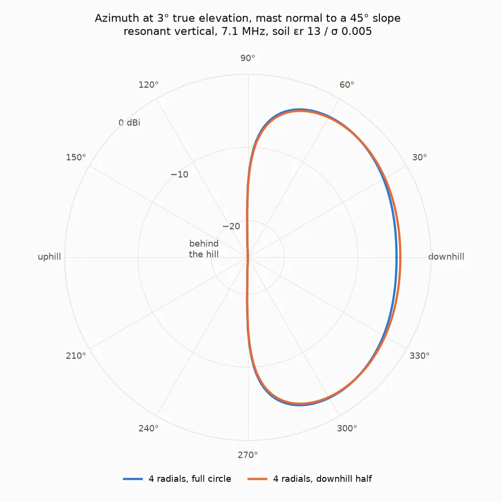
Two things this figure says that the elevation cut cannot:
- Straight down the fall line is not the best direction. That direction sits 48° above the tilted ground, up toward the vertical’s overhead null. The best low-angle directions are 45° to 60° either side of the fall line, where the direction sits lower relative to the ground and nearer the main lobe: −2.8 dBi against −4.7 straight downhill.
- Directly across the slope is dead. At ±90° from the fall line the direction grazes along the tilted ground, where a vertical over real earth always dies: −15 dBi.
So the useful low-angle coverage is a fan of roughly 150° centred downhill with two lobes off the fall line, not a pencil pointing down the hill.
Radials only on the downhill side
Section titled “Radials only on the downhill side”A common suggestion: since the antenna works downhill, put all the radials downhill. The same wire, moved from a full circle into a downhill sector, resonant cut, 45° slope, gain 3° above the downhill horizon:
| radials | R | radiated fraction | downhill, 3° |
|---|---|---|---|
| 4, full circle | 68 Ω | 0.164 | −4.7 dBi |
| 4, downhill half | 74 Ω | 0.153 | −4.2 dBi |
| 4, downhill quarter | 83 Ω | 0.137 | −4.4 dBi |
| 8, full circle | 50 Ω | 0.222 | −3.4 dBi |
| 8, downhill half | 58 Ω | 0.193 | −3.1 dBi |
The suggestion has the right sign and is worth about half a decibel. The mechanism is not the one it assumes. In the ground’s frame the near field and the soil loss are symmetric about the base, and the valley is outside this model altogether. What bunching the radials does is unbalance the horizontal currents in the screen, and the unbalanced part radiates: the pattern skews 0.3 dB toward the radials and 1 to 1.4 dB away from them. It also costs efficiency, since the same wire collects less of the return current when it is not spread around the base. On a 45° slope those net to +0.5 dB downhill, and the uphill penalty is free because that sky is behind the hill anyway. Push the radials into a quarter and the efficiency loss overtakes the skew.
More radials beats placing them: eight all round is 0.8 dB better downhill than four packed downhill.
A plumb mast with radials on the slope
Section titled “A plumb mast with radials on the slope”The build most people mean is a vertical that is vertical — plumb to gravity — with its radials following the hill. In the ground’s frame that is a wire leaning off the normal by the slope angle over a level radial field, so it is not the level-ground antenna: the feed impedance moves with the lean, and the wire’s own pattern tilts with it. The read-out is the same rotation as above; only the solve changes. Two radial conventions are worth telling apart, because they are what an EZNEC user and this catalog would each write down: radials just above the surface (an inch, as a sloper deck over flat radials has them) and radials buried 15 cm.
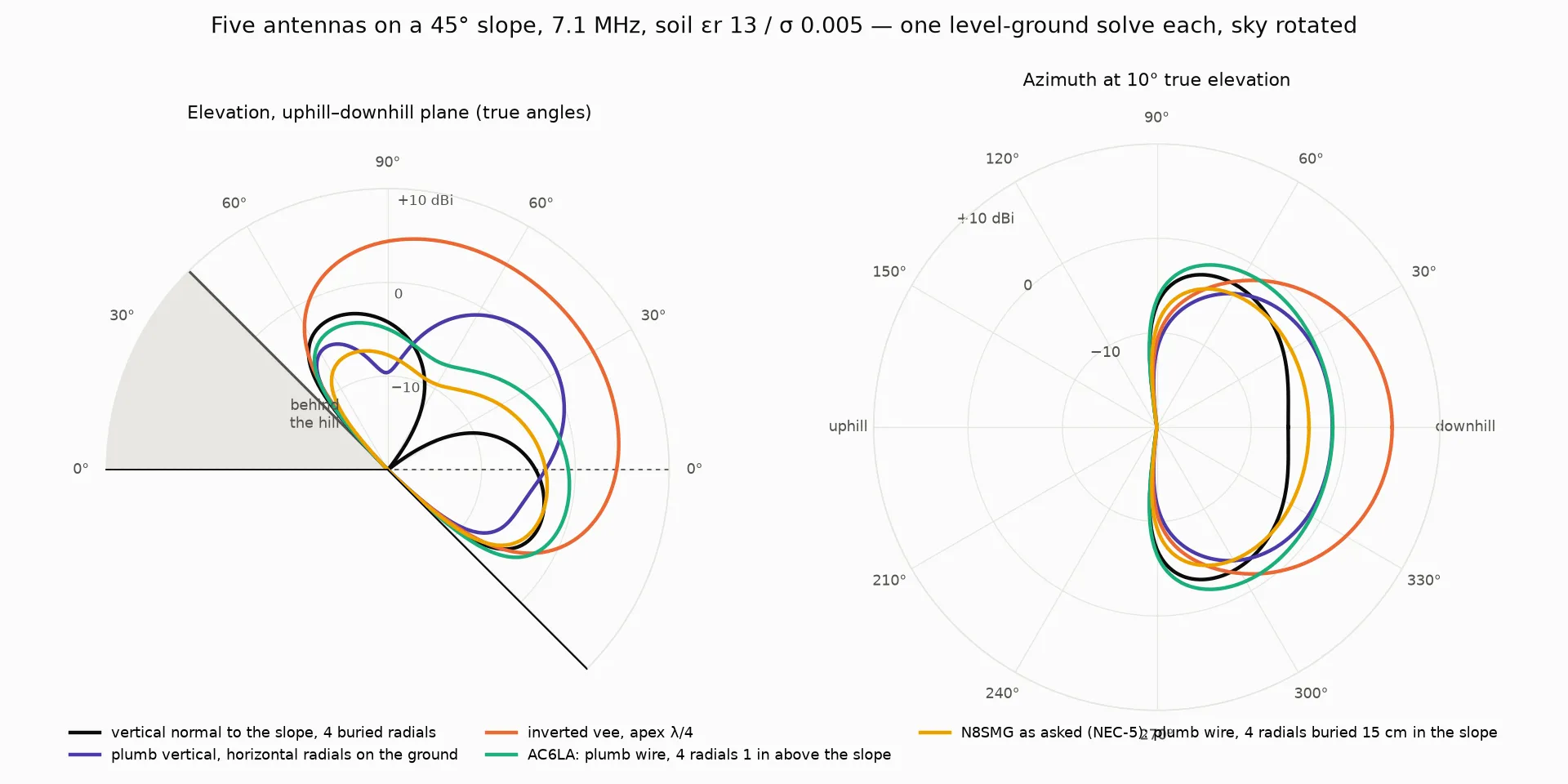
| antenna, 45° slope, 7.1 MHz | R | peak | downhill 3° | downhill 10° | uphill 60° |
|---|---|---|---|---|---|
| vertical normal to the slope, 4 radials buried 15 cm | 68 Ω | −2.8 dBi | −4.7 dBi | −6.1 dBi | −3.8 dBi |
| plumb vertical, 4 horizontal radials resting on the ground | 24 Ω | 1.0 dBi | −2.7 dBi | −1.4 dBi | −5.6 dBi |
| inverted vee, apex λ/4 | 63 Ω | 5.3 dBi | 4.6 dBi | 4.9 dBi | −2.2 dBi |
| plumb wire, 4 radials 1 in above the slope | 27 Ω | −0.5 dBi | −0.9 dBi | −1.4 dBi | −4.9 dBi |
| plumb wire, 4 radials buried 15 cm in the slope | 58 Ω (NEC-5), 55 Ω (momwire) | −2.8 dBi | −3.4 dBi | −3.9 dBi | −8.2 dBi |
The last row’s pattern and gains are the licensed NEC-5’s, read through the same rotation; momwire’s impedance for the same deck is beside NEC-5’s, and the 3 Ω between them is the contact-class residual the two engines carry on every buried screen with a rise to the surface. Every other row is momwire’s. Three things the table says:
- Where the radials sit moves the feed resistance more than the lean does. A straight quarter-wave over four radials an inch above this soil reads about 40 Ω on either engine; the same four radials pushed 15 cm under read about 70 Ω on either engine. Four radials in lossy soil are a lossy screen, which is what Brown, Lewis and Epstein measured in 1937 and N6LF measured again in 2009. The lean then takes each of those down by a quarter: 40 → 27 above the surface, 70 → 58 buried.
- The plumb wire with its radials just above the surface is the best of the verticals downhill, 3.8 dB over the mast normal to the slope at 3°, because it wastes less in the ground and its lobe leans the right way. Bury its radials and it gives back 2.4 dB and lands between the two.
- The vee still wins. At a quarter-wave apex it is 5 to 9 dB ahead of every vertical here at 3° downhill.
A slope is not a hilltop
Section titled “A slope is not a hilltop”The planar model has no valley. Its downhill lobe goes below the true horizon and never comes back, and on a real site that lobe hits ground somewhere down the hill and some of it reflects. That is a different problem with a different tool: the faceted-terrain ground keeps the impedance solve on flat ground and reflects each far-field ray off its own tilted facet. For a mast at a crest with the ground falling away, it gives a different answer from the planar slope — around −0.1 dBi at 3° downhill for a 10° drop, because the specular point walks down the hill and the antenna effectively gets taller.
Its uphill numbers below the slope angle used to come with a warning not to quote them, and the reason is worth stating precisely: below that angle the hill blocks the sky, and a specular model does not know the hill is there — it reports a healthy field straight through it. That is now the diffracted composer’s job, and it is the case it was built for. The same band collapses once the shadow and the crest’s diffraction are in the calculation — by 9 dB at 30° uphill for a quarter-wave vertical mid-slope on a 40 m, 45° hill, and by 4 to 36 dB across the band on the terrain page’s hillside preset at the same slope angle. The terrain page’s charts compose it once the knobs settle. The numbers on this page are the rotated-sky planar model’s, which has no valley and no edge, so its uphill band still is not a thing to quote — the fix lives on the other page.
Which model fits which site: a mast standing on a long uniform slope is the rotated-sky case on this page; a mast at the top of a slope, or on a bench, is the terrain page’s. Neither is a substitute for the other. A hillside, three ways puts this page’s model, the specular facets and the diffracted composer on one 45° hill so the three can be compared line by line.
What each tool can do
Section titled “What each tool can do”- The mast normal to the slope is the level-ground deck in either engine. momwire and NEC-5 both solve it, and both give the same rotated sky.
- A plumb mast on a slope — vertical to gravity, so tilted off the
ground’s normal by the slope angle — is a tilted wire above a buried
screen. NEC-5 takes it, and EZNEC Pro/5 and the app’s NEC-5 lane spell
that deck directly. momwire takes it too, since its crossing fill dropped
a guard that had refused tilted above-ground segments in any deck with a
wire through the interface (momwire#936; the first release after 0.50.0
carries it). The same antenna with its radials lying on the grass (the
catalog’s
surfaceconvention) has no crossing at all and was always ordinary geometry. Measured that way, a 10° tilt moves the feed impedance by about 1 %, and a 45° tilt turns the antenna into a sloper: 46+50j Ω against 61+61j level, with the peak gain unchanged. - The study itself — the rotated read-out, the azimuth ring at a true elevation, the sector sweep, the resonance bisection, and the figures with their numbers in the titles — is a transformation of one solve plus a sweep of variants. That is what a scriptable engine with the far field in hand as an array buys: each script here is under a hundred lines and took its slope and elevation from the command line. The same figures can be built from any engine’s exported pattern table with a spreadsheet and an afternoon per figure; the point is that they did not have to be.